

 Whatsapp
 Message
 USED
USED  CASES
CASES
You Are Here: /
Home /
Gallery Center /
Used Excavators Gallery /
Used Komatsu Excavator PC400-7 Gallery
 Used Excavators
Used CAT Excavators
Used Excavator CAT Backhoe 420F
Used Excavator CAT 320B/320BL
Used Excavator CAT 320C
Used Excavator CAT 320D
Used Excavator CAT 320GC
Used Excavator CAT 323D2L
Used Excavator CAT 330C
Used Excavator CAT 330D
Used Excavator CAT 336D
Used Excavator CAT 340D
Used Excavator CAT 345D
Used Excavator CAT 349D
Used Excavator CAT M315D
Used Excavator CAT 305.5E
Used Excavator CAT 306
Used Excavator CAT 306D
Used Excavator CAT 307C
Used Excavator CAT 307D
Used Excavator CAT 308D
Used Excavator CAT 312C
Used Excavator CAT 312D
Used Excavator CAT 312D2GC
Used Excavator CAT 315D
Used Excavator CAT 325B
Used Excavator CAT 325DL
Used Excavator CAT 330BL
Used Excavator CAT E70B
Used Excavator CAT E120B
Used Excavator CAT E200B
Used Hitachi Excavators
Used Excavator Hitachi ZX75
Used Excavator Hitachi ZX120
Used Excavator Hitachi ZX200-3G
Used Excavator Hitachi EX60
Used Excavator Hitachi EX120
Used Excavator Hitachi EX200-1
Used Excavator Hitachi EX200-3
Used Excavator Hitachi EX200-5
Used Excavator Hitachi EX300-1
Used Excavator Hitachi ZX60
Used Excavator Hitachi ZX70
Used Excavator Hitachi ZX200-6
Used Excavator Hitachi ZX240-3G
Used Komatsu Excavators
Used Excavator Komatsu PC58-8
Used Excavator Komatsu PC200-8
Used Excavator Komatsu PC220-8
Used Excavator Komatsu PC35MR
Used Excavator Komatsu PC55MR
Used Excavator Komatsu PC60-7
Used Excavator Komatsu PC78US-6
Used Excavator Komatsu PC120-6
Used Excavator Komatsu PC128US
Used Excavator Komatsu PC200-6
Used Excavator Komatsu PC220-6
Used Excavator Komatsu PC300-7
Used Excavator Komatsu PC400-7
Used Excavator Komatsu PC450-8
Used Doosan Excavators
Used Excavator Doosan DX140
Used Excavator Doosan DX300
Used Excavator Doosan DX60
Used Excavator Doosan DX225
Used Excavator Doosan DH55
Used Excavator Doosan DH60-7
Used Excavator Doosan DH150LC-7
Used Excavator Doosan DH150W-7
Used Excavator Doosan DH220LC-7
Used Excavator Doosan DH225LC-7
Used Excavator Doosan DH300LC-7
 Used Wheel Loaders
 Used Bulldozers
 Used Motor Graders
 Used Road Rollers
 Used Forklifts
 Used Dump Trucks
 New Truck Trailers
 New Products
 CONTACT US
Used Excavator Komatsu PC400-7 Gallery, Images, Pictures
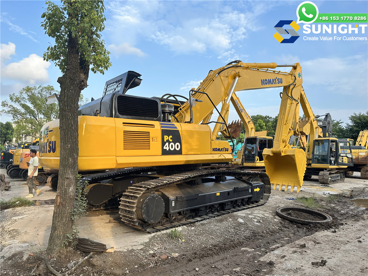


Used Excavator Komatsu PC400-7 Main Parts Pictures
The Komatsu PC400-7 is a hydraulic crawler excavator designed for heavy-duty work in construction, mining, and other large-scale operations. Its robust design, powerful engine, and advanced hydraulic system make it a versatile machine capable of handling a variety of tough tasks. Below are the main parts and components of the Komatsu PC400-7 excavator:
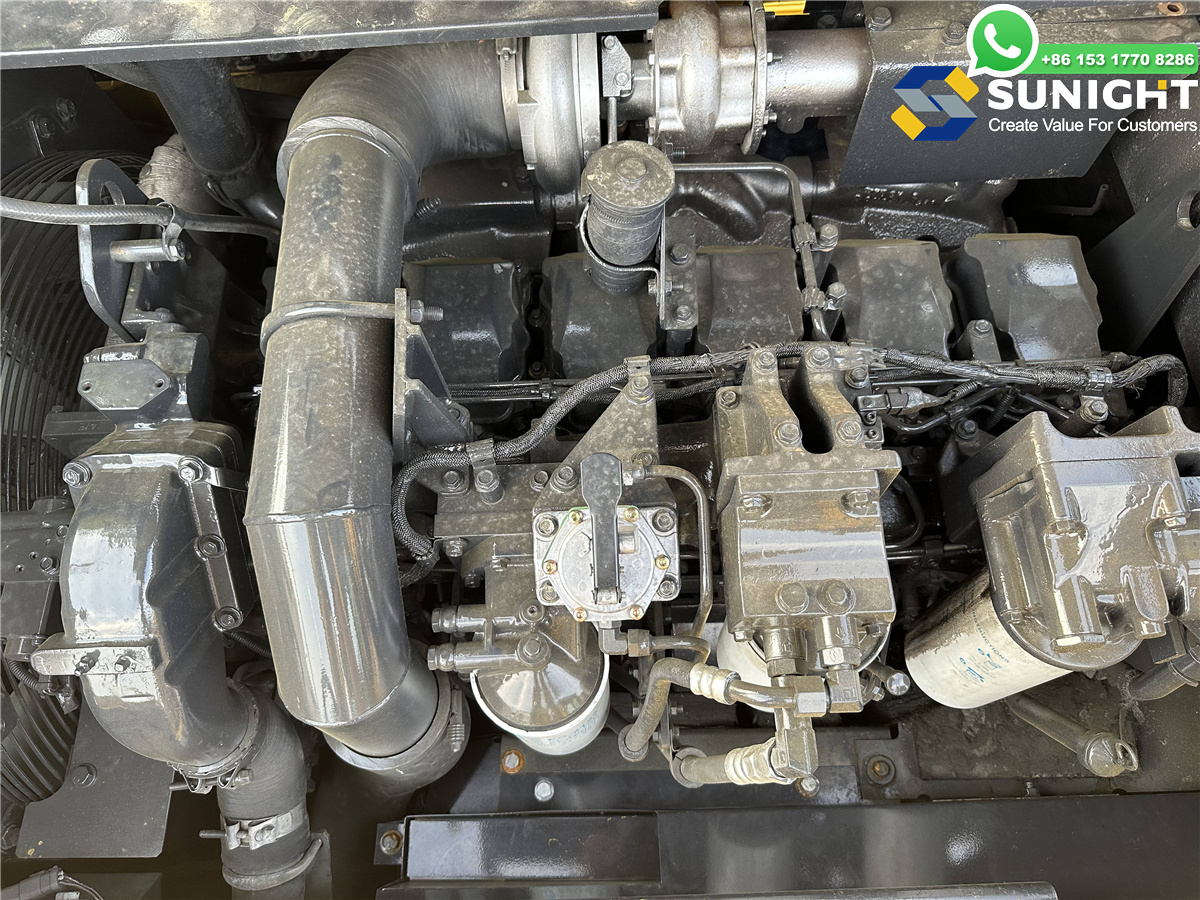
1. Engine
- Engine Type: The Komatsu PC400-7 is powered by the Komatsu SAA6D125E-3, a turbocharged 6-cylinder diesel engine.
- Rated Power: Approximately 261 kW (350 hp) at 1,800 rpm.
- Turbocharger: The engine is equipped with a turbocharger for enhanced efficiency and power, especially under load and high-altitude conditions.
- Cooling System: Includes a radiator, oil cooler, and intercooler to maintain optimal engine temperatures during extended operation.
- Fuel System: The engine uses common rail fuel injection for improved fuel efficiency and reduced emissions.
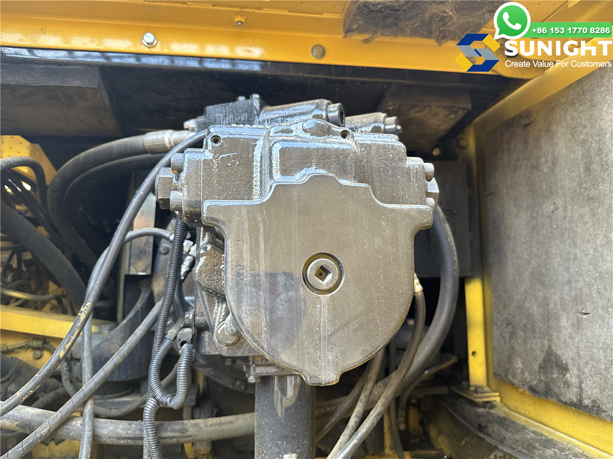
2. Hydraulic System
- The hydraulic system is one of the core components of the PC400-7, providing the power for the boom, arm, bucket, and swing functions.
- Main Hydraulic Pump: The excavator is equipped with a variable displacement piston pump that provides high-flow and high-pressure hydraulic power, enabling it to perform demanding tasks.
- Hydraulic Cylinders: Control the movement of the boom, arm, and bucket. These cylinders provide the force needed for digging, lifting, and handling material.
- Hydraulic Control Valve: Directs hydraulic fluid to various cylinders, allowing for smooth operation of the machine's components.
- Pilot Control System: A pilot control system ensures that the machine responds precisely to the operator's commands with minimal effort.
- Hydraulic Oil Cooler: Maintains the hydraulic fluid at an optimal temperature to prevent overheating during long shifts.
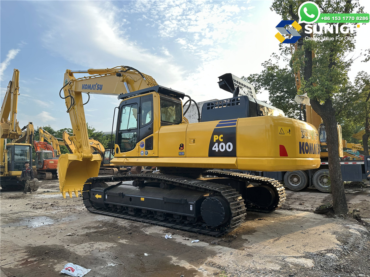
3. Undercarriage
- Track Frame: Provides the base for the machine’s stability and weight distribution. It ensures the excavator operates efficiently on uneven and rough terrain.
- Tracks: The PC400-7 uses steel tracks for durability and superior traction on soft ground, mud, and rocky surfaces.
- Track Rollers: Rollers help distribute the machine's weight evenly across the tracks and reduce friction for smoother movement.
- Idlers: Located at the front of the undercarriage, idlers maintain tension in the tracks and help guide them during operation.
- Sprockets: The sprockets engage the tracks to drive the machine forward and backward.
- Track Shoes: The pads that provide contact with the ground and help maintain traction.
4. Upper Structure
- Cab: The operator’s cab is spacious and designed for comfort and safety, featuring ergonomic controls, air conditioning, and noise-reducing features.
- Swing Bearing: The swing bearing enables the upper structure (including the cab, boom, arm, and counterweight) to rotate 360 degrees, providing flexibility in operation.
- Counterweight: Positioned at the rear, the counterweight helps balance the excavator, preventing tipping during heavy lifting and digging tasks.
- Engine Hood: Protects the engine and cooling system while providing easy access for maintenance.
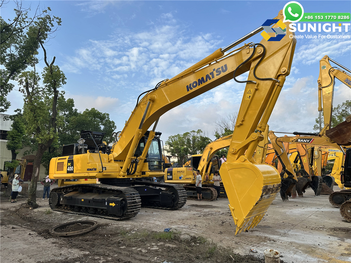
5. Boom, Arm (Stick), and Bucket
- Boom: The boom is a long, strong arm that provides vertical reach for digging, lifting, and other tasks.
- Arm (Stick): The arm or stick connects the boom to the bucket and allows the excavator to extend its reach for deeper digging and more versatile material handling.
- Bucket: The bucket is the main attachment used for digging and material handling. Various bucket types (general-purpose, heavy-duty, narrow, etc.) are available for different tasks.
- Quick Coupler: A quick coupler system allows for easy and fast attachment changes, improving productivity and versatility.
6. Attachment System
- The Komatsu PC400-7 can be fitted with various attachments for specialized tasks. Common attachments include:
- Buckets (general-purpose, heavy-duty, trenching)
- Hydraulic Hammers
- Grapples
- Augers
- Rippers
- The quick coupler system enables fast switching between attachments, reducing downtime and improving job-site efficiency.
7. Cooling System
- Radiator: Cools the engine coolant to ensure the engine maintains an optimal temperature under load.
- Oil Cooler: Cools hydraulic oil, preventing the hydraulic system from overheating.
- Coolant Reservoir: Stores coolant for the engine cooling system, ensuring continuous performance during long operating hours.
8. Electrical System
- Alternator: Supplies electrical power to charge the battery and run the machine’s electrical components.
- Battery: Stores power for starting the engine and operating the electrical system.
- Fuse Box and Wiring Harness: Distributes electrical power to various parts of the machine and serves as a central point for troubleshooting.
- Machine Monitoring System: Displays real-time data on the machine’s performance, including engine status, fuel consumption, and maintenance alerts.
9. Transmission and Drive System
- Hydrostatic Drive: The PC400-7 uses a hydrostatic drive system for smooth, efficient control over travel speed and direction.
- Final Drive Motors: Provide the necessary power to move the tracks forward or backward.
- Planetary Gear System: Helps reduce the speed of the travel motors while increasing torque, allowing the machine to operate more efficiently in heavy-duty applications.
- Travel Speed Control: Allows the operator to control the machine’s speed, optimizing performance in various ground conditions.
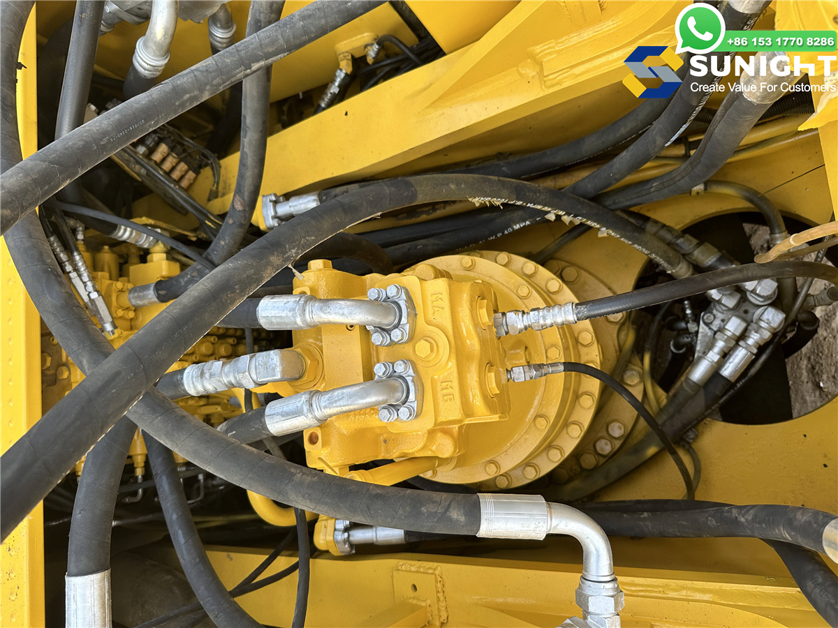
10. Swing System
- Swing Motor: Powers the rotation of the upper structure, enabling the cab, boom, and arm to rotate 360 degrees.
- Swing Reducer: Slows down the swing motor while increasing torque, allowing for controlled rotation of the upper structure.
- Swing Ring: A bearing system that allows continuous 360-degree rotation of the upper structure.
11. Fuel System
- Fuel Tank: Stores the diesel fuel required for engine operation.
- Fuel Filters: Filters out contaminants from the diesel before it enters the engine, ensuring long engine life.
- Fuel Filler Neck: The point at which fuel is added to the tank, typically located on the side of the machine.


Shanghai Sunight Machinery Co., Ltd.
+86-021-68069923
No.196, ZhenPu Road, FengXian District, Shanghai, China
Used Machinery


©SUNIGHT All Rights Reserved. - Shanghai Sunight Machinery Co., Ltd.